A powerful solution for all rotationally symmetric winding
The Cadfil-Axsym package can generate winding programs for all rotationally symmetric components including pipes, spheres, gas bottles, golf shafts, storage tanks . . . the possibilities are endless. The following information briefly describes the basic stages of program generation and shows some of the many features of the system.
Other software options exist for more complex parts such as pipe bends, Ts, and elliptical sections to name but a few of the options.

Mandrel Data Entry
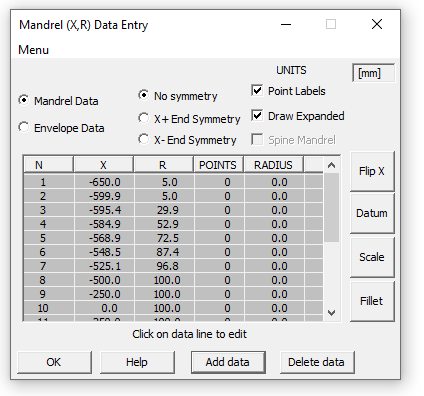
The Mandrel Geometry and winding machine clearance envelope can be quickly entered and modified from a single easy to use dialogue box. The graphics and text windows are automatically updated.
Convex and concave arcs can be fitted between data positions and edited as required.
The clearance envelope allows close control whilst preventing machine collision with the mandrel. For simple shapes an envelope can be automatically created. Options also exist to import geometry via CAD exchange formats such as DXF or IGES.
3-D Geometry
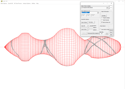
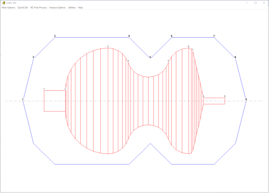
Having created the mandrel geometry the user can interactively create non-slip geodesic fibre paths. Non-geodesic paths can be created using the friction facilities. In this way the user can control wind angles and turning diameters.
The 3D geometry and paths can be viewed from pre-set viewpoints or from any user-defined viewpoint. Check out some of the advanced viewing options.
For parts such as gradually tapered shafts (e.g. golf shafts) the user can generate constant wind angle (non-geodesic) paths using the constant angle option.
Band pattern table

Having created fibre path with two turning points the software calculates the number of circuits required to cover the mandrel based on material parameters such as the fibre band width and the number and type of rovings to be used.
Cadfil now has a material database containing data on many commercially available rovings including E-glass, S-Glass , Carbon and Aramid fibres.
A band pattern table is created (see right) and the user can select the band structure required. If required the number of cycles can be adjusted to give alternative patterns.
3-D Visualisation
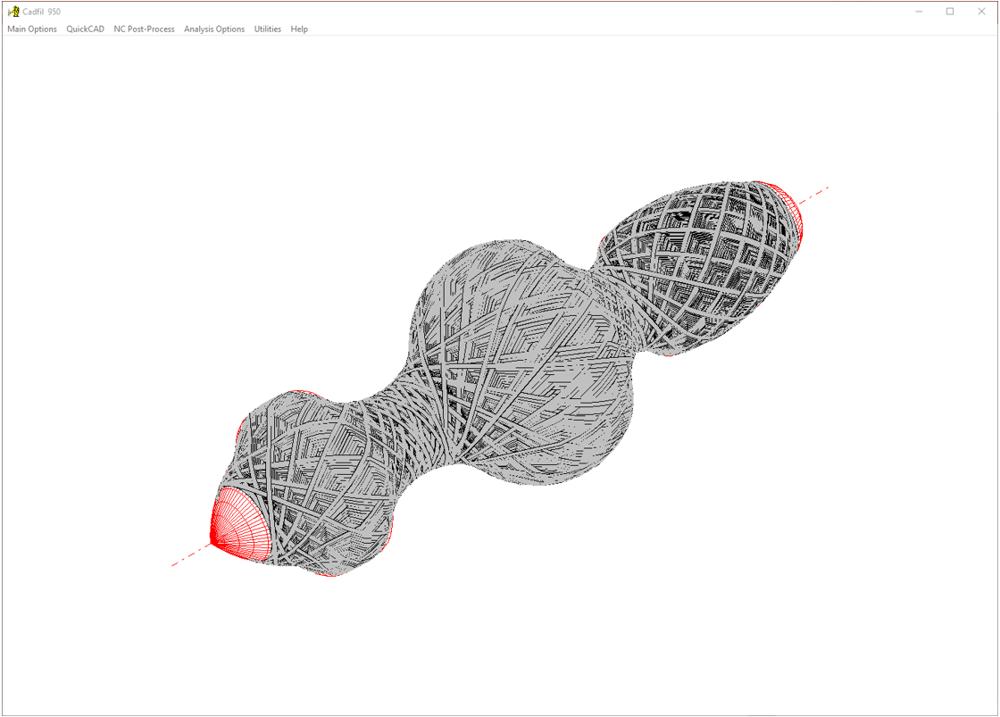
The selected band structure can be viewed in the 3D viewing system (see below).The user is given important data such as a thickness graph of the part and the amount of fibre used. Neutral file interfaces can be supplied to output data for Finite Element Software.
Machine positions are calculated using the envelope and saved to a data file. All Cadfil data files are text files and can be viewed if required.
3-D Animation
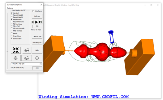
The machine positions can be displayed in 3D around the mandrel or, if required, the user can define the machine fibre dispensing head using brick and cylinder solid shapes and perform a full 3D animation including all machine motions such as eye roll and eye yaw. An example of this is shown in the image to the left.
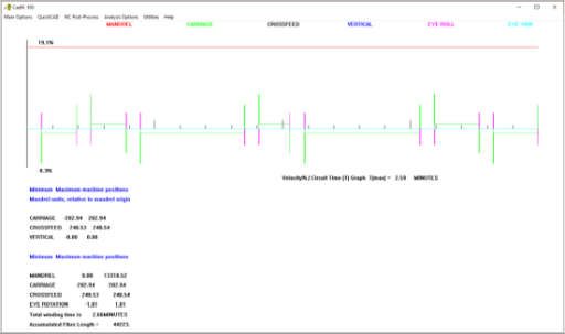
The last stage of program generation is post-processing where the path is converted to machine control data. Numerous control options can be set dependent on the axes available on the machine. Different speed control options can be set to reduce winding time or limit axis accelerations. The software calculates the winding time.
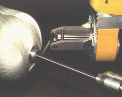
Cadfil is supplied configured for the customer's winding machine. Cadfil can be supplied with multiple machine configurations so that the user can select which machine is to be used. Cadfil can be configured for all filament winding machines types and control systems from 2 to 6 axes of control.
The picture, right, shows Cadfil in action on a 6-axis machine. The Cadfil control strategy eliminates band narrowing over the ends of the vessel.
Cadfil-Axsym also includes QuickCAD options for simple parametric program generation for pipes and dome ended vessels (Cadfil-Lite).
An example of typical NC output.
This varies from machine to machine.
%
O0000
N 10 G01 G94 G105 F 2000
(CADFIL V6.00, DATE 30/10/98)
(PAYOUT FILE NAME NEW3.PAY)
(BAND PATTERN 5)
(NO. OF CYCLES PER LAYER )
( 103)
(NUMBER OF LAYERS )
( 1)
.
.
N	15	G90
N	20	X	-22.14	Y	446.85	B	90.00
N	25	M00
N	30	M21
#1	=	103
N	35	M98	P1030001
N	40	M28
(TOTAL ROTATION : 4257978.425)
(TOTAL TIME MINS: 5.49)
(NO. OF POINTS : 28)
N	40	M22
N	45	M00
N	50	M30
O0001
N	10	G01	G91	F		29000	A		10.46	X		23.46	Y		-22.85	B		-32.83
N	15	F	19877	A		4.90	X		24.87	Y		0.00	B		-21.06
N	20	F	16557	A		3.58	X		18.95	Y		0.00	B		-8.10
.
.
.
N	105	F		15523	A		19.04	X		-75.75	Y		6.62	B		-1.04
N	110	F		26524	A		3.16	X		-5.74	Y		7.64	B		-1.31
N	115	F		27866	A		10.37	X		-14.66	Y		19.55	B		-6.11
N	120	F		27604	A		15.72	X		-13.64	Y		18.18	B		-7.84
N	125	F		21916	A		26.79	X		-9.26	Y		12.36	B		-10.38
N	130	F		18451	A		36.94	X		0.00	Y		0.00	B		-8.32
N	135	F		23042	A		25.78	X		11.10	Y		-14.81	B		-9.05
N	140	F		29000	A		17.70	X		16.07	Y		-21.42	B		-20.84
#1	-#1	- 1
N	145	F		29000	A		2.54	X		3.95	Y		-5.27	B		-6.18	M99
%
