Introduction to payout path creation
 Cadfil Help contents
  Cadfil.com Home
This module maps the fibre path from the surface of the component onto a notional control surface on which the winding machine is constrained to move. The control surface (or envelope) gives clearance around the mandrel, a default payout envelope is created if the user does not create one. In the mandrel edit/create section of CADFIL the user can create a custom machine envelope.
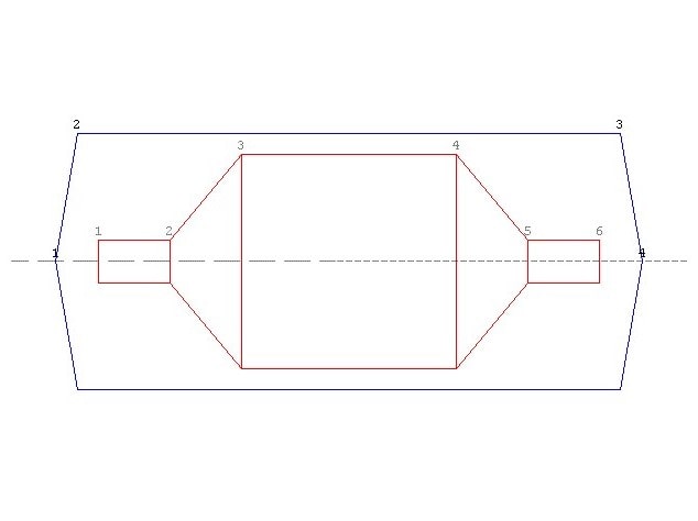
Default Clearance Envelope
In this section the user gives data relating to the materials that he will be using during the winding of the component. From these data the system calculates the fibre bundle cross-sectional area, and by inclusion of the bandwidth will enable the system to calculate the thickness of the composite to be laid down, and the minimum number of cycles for complete coverage.
A feature now exists, which plots the payout eye path, along with the mandrel. This enables the user to view the payout eye motion in relation to the mandrel. Viewing options enable user to view the mandrel and payout path from any direction, whilst also permitting the operator to rotate the payout eye path around the mandrel.
The user can also view the band structure of the winding using the Fibre Bands option
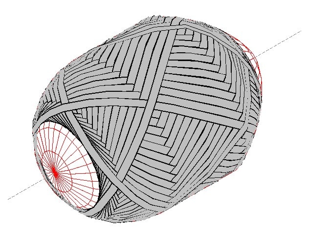
Visualisation of Fibre Band Pattern showing a band pattern 3
The software has the ability to update the mandrel profile. This option enables the user to modify the profile of the mandrel used to generate the fibre path, by adding to it the thickness profile of the layer to be over-wound. This will enable the user to generate subsequent fibre paths onto the modified profile.
Pay ID
When a payout file is generated, Cadfil records an ID number at the start of the top line. This ID number shows how the pay file was created, if it has been generated automatically in one of the QuickCAD parametric options. A list of IDs are below
- 13 Obsolete (CADFIL I TRANSITION PATH)
- 14 Obsolete (ellipse parameteric)
- 15 Cadfil Axsym/'AUTOFIB'
- 16 Obsolete (Axsym pre-version 5)
- 17 ELBOW/MBDUCT
- 18 Plates (standard path, 'PLATES1')
- 19 Plates (hoop path,'PLATES1')
- 20 Spheres (Standard Path,'SPHERE1','SPHERE2','SPHERE3'
- 21 Spheres (join path,'SPHERE1','SPHERE2','SPHERE3'
- 22 Generic Non-axisymmetric
- 23 Pipe Winding ('PIPE1')
- 24 Obsolete
- 25 Pipe Winding (two way hoop,'HOOP1')
- 26 Obsolete
- 27 Pipe winding (Join path,'JPIPE')
- 28 JAVELIN ('JAVELIN')
- 29 Taper Pipe (2 axis no cross feed),'TPIPE1'
- 30 MULTI-HOOP ('MHOOP')
- 31 SPAR (HIGH ANGLE,'SPAR1','SPAR2','SPAR1','SPAR2','SPAR2','SPAR1' ]
- 32 SPAR (LOW ANGLE)
- 33 Obsolete, Dome vessel (non geodesic,'VESSEL1')
- 34 Obsolete, Dome vessel (JOINING PATH, non geodesic,'VESSEL1')
- 35 Taper pipe 3 axis with cross feed, 'TPIPE1')
- 36 Reducer ('REDUCE1', 'REDUCE2')
- 37 Vessel With End-caps ('VESSAL3')
- 38 Edge winding cone ('EDGEWND')
- 40 Incremental motion data, manual input
- 41 Tee option 1
- 42 Tee cross piece pipe wind
- 43 Multihoop at general pipe orientation - used for elbows 'EMHOOP '
- 44 Same as 15, new format
- 45 Same as 13, new format
- 46 multihoop with non-default mandrel,'MHOOP2'
- 47 Vessel with End-Caps join path
- 48 general pay path from imported step file curves (CADCRVS )
- 49 isogrid winding ('TRS001')
- 50 AFP (axsym fib path for AFP)
- 51 MultiHoop flood fill
these numbers can also be used in aspects of machine configuration. For example using $AX-2-TYPE-OFF, you can disable eye rotation for hoop winding type programs,which can be useful if winding using tapes.