Cadfil Parametric Pipe Winding Example - PEX01
 Cadfil Help contents
  Cadfil.com Home
Introduction
This example makes a set of winding programs for a pipe using the QuickCAD
parametric interfaces. This example forms part of the examples that can be found in the Cadfil help system.
The programs is made from of a number of elements which
cover most of the common types of winding for winding of cylinder (without
recourse to winding onto end-caps). The Parametric options used are:
1] "Multi-Hoop Winding" - hoop for "90 degree" winding for a full length pipe
2] "Pipe Winding" - for a helical winding of +/-45 degrees
3] "Pipe Joining Path" - to allow continuous winding between program elements that
would otherwise be discontinuous
4] "Multi-Hoop Winding" - for a localised thickening half way along the pipe
Pictorially the winding programs are shown in the 4 figures that follow:


Step 1, Hoop winding.
We first create the hoop winding, which is a high angle helical path with a pitch based on the width of the fibre band. This creates a full layer with only one pass of the winding machine. The mandrel is 7000mm long and we wish to make a pipe that 6000mm long. The mandrel is of outer Radius 300mm (600 diameter) and we wish to have a machine clearance of 50mm so that gives a Clearance radius is 350mm. The width of the fibre band which is made of of several glass rovings is assumed to be 50mm. The point spacing and mandrel direction were left at the default values. This data can be seen in the left part of the following windows dialog.
The central column of 'position' fare are axial positions, the winding progresses from one axial position to the next. In this case we start at position 500 and end at position 6500. In fixing these positions we have defined a 'zero' or datum position somewhere on the mandrel. it is logical to ensure the zero position is somewhere that is readily identified that you can measure from when location the mandrel in the winding machine. The initial 'dwell' is a rotation with no axial motion at the position. Having 360 degrees of rotation 'squares off' the end of the winding but this value can be zero or any other positive value.
It is Important that "The No. of X positions" value matches the number of rows of data that are being used. Setting a lower value will lose some of the data and not give the result you are expecting!

Having entered the data parameters for the Multi-Hoop winding we can "Save" the data (for this example the name pex01mh1 was used (Pipe example 1, Multi Hoop 1) but any name is OK. It is however useful to use some logic in the naming as it can save a lot of confusion later. The file is saved as .par (parameters) and like ALL Cadfil files is a text file that can be viewed on Notepad.exe. The Calculate button creates the payout path file (.pay) and opens the payout file viewer. Having used the viewer and then "Quit" from it this the next step is to created the helical winding at 45 degrees to cover the same area of the mandrel. This is by selecting the "Pipe Winding" option from the "QuickCAD" menu.
Step 2, Helical Winding.

The data parameters used can be seen in figure 6 above. The Cylinder radius and clearance radius are the same as for the hoop winding. Because the hoop winding finished at axial position 6500, we make this the start position. As the winding is in the negative direction along the mandrel we make the wind length negative, in this case -6000mm.
The winding angles was specified at +/-45 degrees. The convention is that 0 is axial and 90 is circumferential (hoop). The parameters are saved to the file pex0145.par, when we click calculate the next step is to "select the band pattern".

The band pattern table for this particular wind is show in figure 7above. The key points. To discuss are:
- Band pattern is required to ensure the mandrel is covered evenly around in a structured way
- Band Pattern adjusts the total rotation of the circuit
- Dwell Winding adds rotation at the end
- Progression winding Adjusts the rotation by proportionally adjusting all rotations this may increase or decrease the overall rotation.
- The table is ranked such that the pattern at the top of the table has the smallest adjustment of the rotation
- The dwell split function can bias dwell rotation between the two ends
- The help topic gives more information
- The Cadfil text window shows the 'turning' length and the length that remains i.e. that part that is at +/-45
- Higher friction values reduce turning length (proportionality)
- Turning lengths are proportional to diameter
- Is is possible to adjust the number of cycles to influence pattern choices, this can cause gaps/overlaps
We select a band pattern by clicking on one of the lines of data and then clicking 'OK', for this example the top option was picked. The next step is to create the localised hoop winding as shown in Figure 8.
Step 3, Localised Hoop Winding.

The Multi-Hoop Dialog is used again. The Parameters are shown if Figure 8 above. A quick way is to open the previous Multi-Hoop data (pex01mh1.par) and then save as a new file (pex01mh2.par). We then change the position, rotation values and update the number of positions to 5. You can note we go from position 3500 to position 4000 then back to 3500 (2 layers) and repeat again to give a total of 4 layers. With a thicker build up it is often better to 'feather' the edge so the extent of later layers is reduced slightly. If you are mathematically/IT inclined there is an example of an Excel spread sheet in c:\Cadfil\Cadfilxxx\data\mht2.xls where xxx is the Cadfil version) that shows calculated data for a series of layers using a mathematical progression. The data can then be saved as a text file with the .par extension and read by Cadfil. We save the data again and calculate the payout (.pay) file.
Step 4, Combining the winding files

This far we have created three individual .PAY files each of which could be post processed to produce a winding program for the Filament winding machine. If we did this we would then need to edit them together to make a complete program, or we would need the run each program in turn on the winding machine. Cadfil has a means of combining these programs using the "Combine Programs" option on the "NC Post-Process Menu". Figure 9 above shows this option. Using the "Add" option the three pay files are picked in turn. We are asked the number of times to repeat and the position for the program and in all cases we except the defaults. The position by default adds the new file to the end of the list. Some key points for discussion are:
- Note the start position and end position in the end two columns
- If start and end are the same the program could be repeated (we could have set the number of repeats)
- The end of the first program matches the start of the second program
- The end of second program does not match the start of the next program
- We would drag the fibres over the mandrel surface, a joining path is needed
- If we click "Finish" the list as saves a file-name.ctl, for the example I used pex01.ctl.
Step 5, Creating a Pipe Joining Path

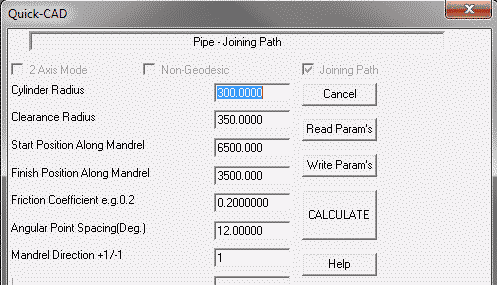
We can create a joining path Using the QuickCAD menu "Create Joining Path Option", The Parameter are shown in figure 10 above. This is very similar to the Pipe winding parameters except we just need to specify that start and finish positions. In this case from Figure 9 we know we need to start at position 6500 and finish at position 3500. It is worth noting that we have used the same clearance radius throughout, this is not essential but if we use a different clearance values the winding machine will make a radial position adjustment at the start of the next program. This is because the programs normally start with an absolute position coordinate (G90 on a G-code controller). This joining path was saved as pex01jn1.par. As always the final step is "Calculate" and then to view the .pay file

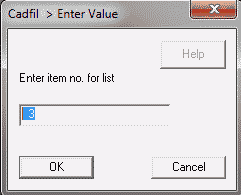
We now need to added the joining path Using using the "Combine Programs" option on the "NC Post-Process Menu" as before. On the dialog (Figure 9) we select "Open" and pick the previously created combined winding file pex01.ctl. We then need to "ADD" pex01jn1.par noting that we must add it at position 3 (Figure 11) not as the last position as that would be position 4. We then have the result as figure 11, noting all the finish and subsequent start positions now match. We now save the pex01.ctl file using the "Finish" Option.

Step 6, Creating the NC data - Post-Processing
The last step is NC post-process, These stage is not discussed in detail in this example as it is a generic example and post-processing options can be quite specific to the winding machine settings. The keys steps are however:
- You must select the pex01.ctl file to post process
- The Xdat (X-datum) value is important as this relates the Zero position of the mandrel to the zero position of the machine.
- In out example the zero position was the left hand end of the mandrel so we need the distance from the reference position (often the chuck face)
- There are usually questions relating the machine speed settings
- there are often questions quite specific the the machine and or controller
- Having created the NC files these can be transferred to the winder of winding
- Using some combination of the tools described in this example many different type of tubular part can be made.
- The complete winding can be viewed from the Main Menu, "View Multiple payout files" option. The .ctl file is selected.
- Individual .pay files can be viewed from the Main Menu, "View payout files" option. The .pay file is selected.