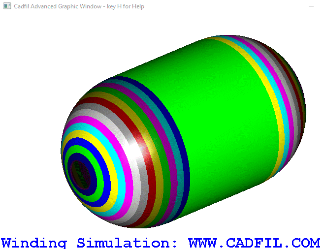
Shell model Via Continuous Grid Mapping (CGM) Method (Beta)
 Cadfil Help contents
  Cadfil.com Home
Grid Mapping (CGM) Method Overview
Access to these option via the Cadfil FEA Dialog and a general discussion of all FEA interface options in Cadfil can be found in the parent topic Cadfil Finite Element Analysis Interface Module
This is a entirely new methodology for FEA model creation based on new technology introduced in Cadfil V9.66. All previous models are based on thickness files (TH2) which have calculated (for each filament wound layer) an average thickness for each axial position along the mandrel. This thickness file method is applicable only to rotationally symmetric parts. With all FEA methods some approximations are required, for example a geometry is approximated as being represented by a collection of elements of uniform property. The averaged (uniform) thickness is for the most part a reasonable assumption but is not necessarily reality. A winding layer is in fact a series of bands that are placed on the surface of the mandrel. If we consider the band (like a tape) of having a width and a constant thickness (t0) then at any point on the mandrel the thickness will a whole number (1, 2, 3,.... N) multiple of t0. Consider the three picture shown below. The in the new technology method you can see a complex variation of thickness on the dome as the bands progressively overlap more an change direction. The new technology is based on processing path files (.pay) sequentially laying the bands as they are during the actually winding and accumulating the thickness and direction information as it goes. As such, this method can process non-axisymmetric paths and can also include the material laid down in single transition (joining paths). Because the fibre structure is much more realistically represented than with using a traditional laminate description a suitable FEA system can much more accurately represent the the fibre structure and use multi-scale approaches for more accurate prediction of failure.
Currently this option is supported using new features implemented in Altair OptiStruct and Hypermesh in the 2022 versions (and late 2021 versions). The laminate can be created on an imported shell models that is a basic shape match matches for the Cadfil Winding model, or Cadfil can create a shell model based on divisions of a master mandrel and a number of elements for the revolve. As well as the normal Mesh with GRID and CQUAD/CTRIA elements cards we have STACK, PLY, PCOMPP and DRAPE cards that describe the winding. STACK defines a winding sequence which consists of a number of PLY names which relate to filament would layers (FWL) from .PAY files in Cadfil. The PLY entries pull together material data basic ply (tow) thickness, element sets and DRAPE tables for each PLY (FWL). Finally the DRAPE table for each element in the relevant element set has the number of tows/bands that cross the element centre and the direction of those tows. This leads do a coherent hierarchy in Hypermesh and the user is able to edit filament wound layers, to add, delete duplicate and change the band thickness and material.


Cadfil FEA Interfaces data input fields required for CGM
The parameters of a Cadfil FEA interface job are discussed in detail in the parent/main topic, an image of the dialog is shown below. Not all parameters are used or required for the CGM but some are essential. This section gives a basic overview of this. It is import to note that the CGM does not use the Cadfil thickness (.th2) files it uses the actually winding paths on the surface of the mandrel in the sequence they are actually laid down. It looks directly at the area that is covered by each individual fibre band. If the fibre structure had gaps between the band then these gaps will have no fibre if a grid point for calculation lies in such a gap. As such instead of a thickness list file a combined winding file (.ctl) is used which is a sequence of payout path (.pay) files. Note that if the combined winding has joining paths the individual paths that join will also be included as part of the fibre structure created in the drape tables. The CGM option when selected via the tick box of the FEA Dialog is EXCLUSIVE of all the other tick box options, that is, if it is selected it will be the only option processed. If you also want other options then save the parameters as a different name and then change the option selections and also deselect CGM. Note also that the Transformation options, options, element node order, boundary condition options (loads and restrains) all can be used if required. The mesh used will be either the Cadfil mesh from the master mandrel or an imported mesh. If the imported mesh box has a valid model file name it will be used, if is left empty the master mandrel data will be used for the model.
