Plate parametric data entry
 Cadfil Help contents
  Cadfil.com Home
No. of points on turn radius.
This parameter (NPT) is an integer (whole) number that must always be odd (i.e. 7,9,11....). The programmed fibre path on the mandrel surface assumes that the end of the edges of the plate are round with a radius equal to half the plate thickness. This results in a smoother machine motion when winding, and reduces 'snatching' of the fibre that could cause fibre breakage. It is not important for the mandrel to actually have rounded edges but some radius is recommended on the plate edges, as a sharp corner can cut the fibres. All the data points on the winding paths are on the rounded ends (the path across the plate is always a straight line). This parameter is the number of data points in the fibre and payout track around the mandrel edge. There will be 2*NPT data points per mandrel rotation when winding. For accuracy the software does not allow a value for NPT of less than 7, if a value of less than 7 is used the software will warn the user with a message and then actually use a value of 7. If an even value of NPT is used, the software will warn the user and will use a value that is 1 greater.
Advance Parameter (IADV)
The is an integer value and takes the values 1 or 2. If one is used the required wind angle is only given on one face of the mandrel. The other face will have a wind angle of around 90o.
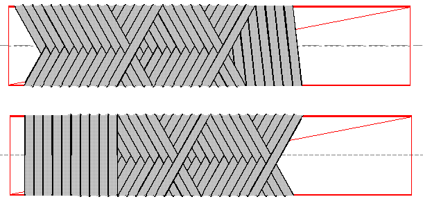
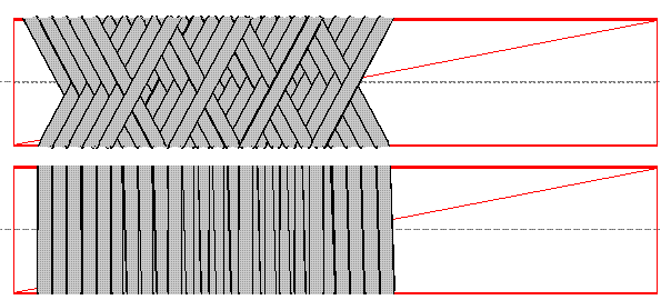
If a value of 2 is used (see figure below) the wind angle is given on both faces, but the length of mandrel required for a specified sample length will be much longer. Mandrel length is an issue if the mandrel is to be rotated about both axes as the length cannot exceed the maximum machine capacity for diameter. For wind angles that are less than about 60o slippage at the plate ends may occur when the wind angle is on one face only (see below figure for IADV = 1), and therefore the wind angle must be specified for both mandrel faces in this case (IADV = 2).
Front & Back faces of plate with face advance parameter 2

Front and Back faces of plate with face advance parameter 1

Wind angle (THETA)
The wind angle specified is always the angle relative to the machine carriage axis. For example, 90o is hoop fibres and 0o is axial fibres with respect to the machine carriage axis. The advance parameter above can be set to give this wind angle on one or both mandrel faces. The wind angles achieved will depend on the options set. The software displays on the screen the wind angles that will actually be used. These angles are referred to as
THETA1, THETA2, THETA3 and THETA4 these are as follows:
THETA1 Wind angle on front mandrel face on forward carriage stoke.
THETA2 Wind angle on rear mandrel face on forward carriage stoke.
THETA3 Wind angle on front mandrel face on return carriage stoke.
THETA4 Wind angle on rear mandrel face on return carriage stoke.
If hoop winding (90o) is required the user can specify THETA as 90o. The software will automatically generate wind angles such that the carriage advances one fibre band-width per mandrel rotation. Read the special notes on hoop winding.
Plate Dimension and Clearance parameters

Required Wind Length (WLREQ)
In general there will always be some scrap material at the ends of the winding. The software will generate a winding program that gives the +/- winding angles over a rectangular area that is the Required Sample Length x the Plate Height. In some cases a longer sample of full +/- winding can be cut from the plate but of reduced height .
Fibre Band width (BWID)
The band width is the actual width of the filamentary material that is being wound onto the surface. It is usually specified in mm. Large band widths will lead to less flexibility in exactly obtaining specific wind angles as the band progression will be greater.
Plate Height (PHITE)
Plate height is the mandrel rotating diameter when winding, and is usually defined in mm. This value must be correct for accurate generation of winding programs (see Figure).
Plate Width/Length (PWID)
This value is the length of the plate (along the machine carriage direction when winding) and is usually in mm. The value is used for checking that the mandrel is sufficiently long for the sample size requested (see Figure). It is also used for location of the carriage over-travel limits (see CLREND)
Plate Thickness (PT)
This is the thickness of the plate used, usually in mm. It us used in the calculation of mandrel clearance, and for the radius assumed at the plate edges (see Figure). The axis of rotation of the mandrel is assumed to pass through the geometric centre of the plate.
Top, Side and End Clearances (CLRT, CLRS, CLREND)
The calculated machine positions in the .PAY file lie on an elliptical surface (See Figure) around the mandrel when view end on (along the carriage axis). This allows close control over the fibre whilst allowing clearance to be made between mandrel and delivery system. There are three parameters, Clearance Top Edges, Face Clearance and End (overshoot) clearance. These are shown in the diagram above. These values are normally in mm.
Start Position from Plate End (XSTART)
This is the location of the start of the winding pattern on the plate relative to the most negative edge of the plate (with respect to the carriage axis positive direction) and is normally in given in mm. By changing this value, the position of the winding on the mandrel can be changed. This parameter permits a positive or zero value, however if a negative value is specified the program will automatically fix the program start position such that the centre of the usable sample is at the centre of the plate. This facility is useful if a number of different wind angles are used as the usable portions of each program will thus have maximum overlap.
File stem name
The first line on the control file contains the stem name for the data files the software will create. For example if the name was PLATE1 the software will create output files PLATE1.FIB and PLATE1.PAY and the default NC data file will be PLATE1.PRG. Because this item is read as text, no text should follow on the same line as this data item.
The user should now select the POST-PROCESS option. Post-processing as exactly as for the CADFIL software with the following exceptions:
1)The user is not asked to select a band pattern as this has been pre-determined by the software.
2)The software allows the program cycle to have a different carriage position at start and finish to allow for band indexing along the mandrel.
3)The initial codes may be different for the program start position as unlike standard axisymmetric winding the initial rotational position of the
mandrel is very important.
Details on the use and configuration of the post-processor can be found in the CADFIL user manual. See also, notes on combining winding programs and special considerations for hoop winding programs.