The Cadfil Pipewinder (QuickCad - Multi-Pipe Option)
 Cadfil Help contents
  Cadfil.com Home
Pipe-Winder Overview
The Cadfil Pipe winding software is designed for higher angle winding (40-90 degrees) on pipes and is ideal for use on 2 axis winders. When Pipe-Winder is included as part of a higher specification package(e.g. Cadfil-Lite) then more machine axes may be available. Multi-layer and angle winding patterns can be quickly generated with both hoop (90 degree) and helical winding. Standard Pipe winding is not suitable for low angles (less than 30 degrees) as this involves winding over an end-cap, however lower are possible using the pin winding features that were added a V9.93. For winding over end domes use Vessel with endcaps of CAdfil vessel design packages. The thickness of the winding and winding times are automatically calculated. Each layer is calculated making allowance for the thickness of the previous winding to ensure band pattern and fibre angles are always optimum. For each later the turning length at the end where with winding angle is changing for the turning around is automatically calculated. For some applications this length is considered as waste as it is cut away after winding. As of Version 9.09 there are additional columns that give the 'good length' i.e. the part of the layer that is, at the angle that you asked for, as well as the axial positions of the ends of the layer are given. If the new "Calculate constant good length" box is ticked Cadfil finds the layer that has the longest turn (waste) length and then using the total wind length from the header data calculates the 'good' length. Then for all the other layers the length becomes the turn length plus the good length. In this way material is saved if the ends of the finished tube are to be cut away. the result of using two layer sample data in the dialog above is shown in the picture below.

In the picture above in first green layer is followed by an automatically created joining path and then a single, much short (blue) hoop layer.
This software is driven from a single dialog screen. As of Version 9.09, it has the feature to minimise waste by automatically reducing the lengths of layers that have shorter turn-around lengths. The image below is from Cadfil V9.51, optional length offsets are added. These can be used to adjust the length of a layer from the general length set so if values of 100mm and 200mm were set for a layers the pipe layer length will be reduced by 100m a the first end and 200mm at the second end. The offset can be negative. Such adjustments are often made to reduce the large 'dog bone' build up of thickness at the end of the wind.
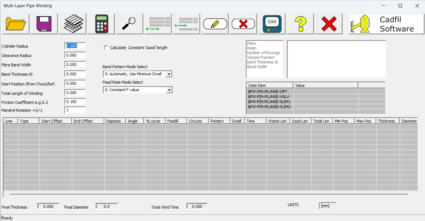
Creating a program (overview)
Creating a program with pipe-winder is simple. There is a single window dialog box (data entry screen) shown above. The steps for program generation are:
1) Enter the Header Information, these are all defined below if more information is required. The header information is basic information such as mandrel diameter and the fibre band width that is constant for each layer. After you have done this, we would recommend using the Save button to save these parameters
2) Click The Material Data button to activate select your winding materials.
3) Click The Add layer or Insert layer buttons to create a new winding layer or Double click on a filled or blank line also activates add or edit. A separate dialog box to input the information, as shown below. Add layer will add a new layer at the bottom of the list, whereas Insert layer will place it on whichever line in the table is selected, moving any subsequent lines down. For more information on the parameters to input here, see the Layer Data Explained section below
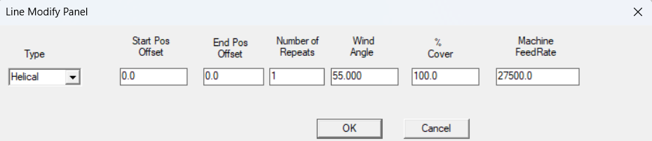
4) Layers can be deleted using the Delete layer button or a edited using the Edit Layer button. When deleting a layer, the selected line is deleted. You can edit a line by either selecting the line and clicking the Edit Layer button, or by simply double clicking the line you want to edit.
5) Click the 'Calculate(update)' button to fill out calculated values in the data table. You will be asked to save the data and must give a file name. Error messages will be given if data is incorrect or missing. You must correct the data. At this point you can also use the 'View' button to either view an individual layer (if a line is selected), or view all layers (if no line is selected)
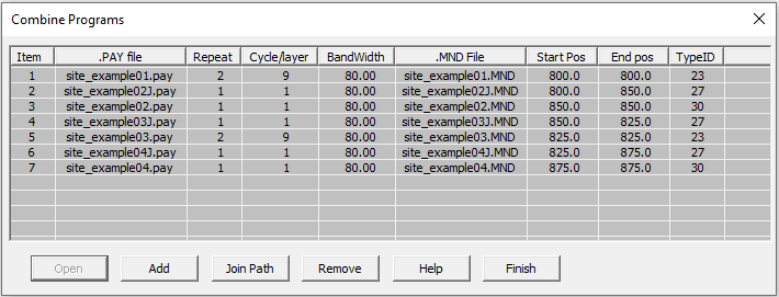
6) After a successful Calculate (update)the Generate NC-Data button becomes active, click this to generate the complete winding program, after NC generate the wind times are added to the table. You get an option to view the program in the default text editor (normally notepad). The process creates a number of data files, the parameters entered are saved in a .par file. For each layer we automatically create a payout path(.pay) and mandrel (.mnd) file. If any joining paths are needed .pay and .mnd files are created for these also. Finally a combined winding file (.ctl) is created for the post-processor. For the parameters shown in the example earlier in this topic the .ctl file is shown below opened in the combine programs dialog. The parameter file was given the name "site_example.par", all the other files are created automatically. Note that an advanced user could take this .ctl file and add of program elements created by the "Pipe", "Multi-Hoop" or "Pipe-Joining" parametric options.
The Multi-Pipe 'header' data
The 'header' data is the parameters on the left side of the dialog, used to define the mandrel, and some features of the winding. Each of there is explained in more detail below.
Cylinder radius. Is the radius of the mandrel at the start of winding. If the mandrel diameter is 200mm the radius is 100mm.
Clearance Radius is the distance of the payout head (fibre comb or similar) from the mandrel rotation centre, so if the mandrel radius was 100mm and the clearance radius was 150mm the machine payout head will be 50mm (150-100) from the surface of the mandrel. For machines with more than 2 axis this position can be set automatically in the NC code. For 2 axis machine this must be set manually or a value that is possible (or fixed) on the machine must be entered. If the machine is a large distance from the mandrel accuracy will reduce (variation in wind length and band structure). For large mandrels (more than 1m diameters) a surface clearance of 250mm (10 inches) is OK. For small mandrels (<300mm diameter) a surface clearance of 50-75 mm (2-3 inches) is OK.
Fibre band-width is the true width of the fibres band as it lays onto the mandrel, if you considered it as a tape.
The Band thickness is the thickness of the fibre band as it lays down on the mandrel if you consider it as a tape. One way to measure is make a single layer of hoop and the band thickness is half the increase in mandrel diameter.
Start position. This is the position along the machine carriage where the winding will start. It is measured from a fixed position often the machine chuck face or headstock. This reference is set up in the post-processor configuration file. Your machine supplier or software supplier should be able to advice/or set up this file.
The total length of winding is exactly what it says. This included any turning length so if you need a length of tube with an exact wind angle all the way along it you will need to use a longer wind length to allow for the turning length. The waste is automatically calculated. So if you want say 2000mm at 45 degrees enter this data and 'calculate'. If the waste length is given as 200mm then increase the total length of winding to 2200mm. If a negative length is used the winding will start in the negative direction of the carriage, so the start position must be specified to suit this, there is a diagram later in this document. If the new "Calculate constant good length" box is ticked Cadfil finds the layer that has the longest turn (waste) length and then using the total wind length from the header data calculates the 'good' length. Then for all the other layers the length becomes the turn length plus the good length.
The friction coefficient is used to calculate the turning area. Cadfil supplies a default value but this can be changed by the user. If friction is increased the tuning lengths get shorter but if too high a value is used the fibres will slip. Typically a value of 0.1-0.2 is used.
Mandrel rotation +1/-1 is the direction the mandrel rotates, a value of +1 (default) give positive(+) mandrel rotation, -1 gives negative (-) mandrel rotation.
Layer Data Explained
The layer data is shown in the main table. This shows all of the information for each individual layer. New layers can be made using the add or insert buttons or deleted with the delete layer button. The data items are described below.
Line is simply the line number, where the first line number will be 1, increasing by 1 each line. This allows you to quickly see the total number of layers.
Type. This tells you if each layer is either hoop or helical. If hoop is selected when creating a layer the wind angle will be calculated to give a helical lead of one band with. If you wish the Bands to overlap or gap for a hoop winding use the 'cover factor' parameter. Helical winding creates a +/- layer at the wind angle specified by the user.
Start/End offset allows the starting or ending position to be modified for a single layer. The start offset is added to the start position, and the end offset is taken away from the end position given by the stated 'Total length of winding'. If the 'constant good length' option is used, these offsets are calculated automatically for most efficient fibre use, and to minimise waste fibre.
Repeats allow the layer to be repeated a number of times. For example with a helical winding setting 3 gives 3 +/- layers. It is not good to set the number of repeats to high numbers as the mandrel radius increases with each layer and the wind angle will thus change slightly with each repeat layer. Eventually gaps will start to appear between the bands. This effect is more pronounced if the mandrel has a small diameter as the change in thickness with each layer will be proportionately more. For hoop winding each layer is a single traverse., if an odd number is specified i.e. 1,3,5 the next layer will start at the other end of the winding length.
Angle is the helical winding angle in degrees, 0 is axial 90 is circumferential (hoop). For simple pipe winding (no end caps) angles below 40 degrees are not advisable as the turning length (waste) increased dramatically.
% cover is 100% by default but the user can over-ride it. This can be used to 'adjust' the band width. If a cover factor of 200% is used the programmed bandwidth will halve so the bands will overlap. For a cover factor of 50% the winding will have gaps. During winding the bandwidth may be slightly different for different wind angles so the user can adjust for this here if required.
FeedR, or Machine feed rate is the winding speed for each layer. The default value is from the machine configuration file. The winding machine supplier should assist in the setup of this file.
Circuits, is a calculated value of how many circuits the winding program requires to complete one full layer. For hoop winding this is always 1, for helical winding it is calculated automatically.
Pattern, or Band Pattern Number is the number of 'starts' and is explained in further detail here. There is no pattern as such for hoop winding.
Dwell is additional mandrel rotation at the ends to make a particular band pattern work correctly. The amount of dwell can be minimised by keeping the default band pattern selection mode (mode 0).
Time is the layer wind time, a total is shown at the bottom. Times are calculated at NC generate stage.
Waste length is the length out of the total wind length used for turning, where the wind angle is not true. Half of this amount will be at each end.
Good length, conversely, is the length out of the total wind length where the wind angle is true, and at the specified angle. This can be calculated as the Total Length for the layer minus the Waste Length .
Total length is the full length of winding for that complete layer, including turning zones.
Min Pos/Max Pos are the minimum and maximum x positions for that layer. They can be calculated by taking the minimum and maximum positions for winding in total (given by Start position and Total length of winding), then adding any start offset to the start position to give the minimum for the layer, and subtracting any end offset from the end position to give the maximum for the layer. These are automatically calculated.
Thickness is the cumulative thickness of the winding after each layer, using the sum of the thickness values for every layer up to that point. The thickness of each individual layer is calculated using the band thickness multiplied by the number of repeats and the % coverage.
Diameter is the total cumulative diameter of the pipe. The diameter is measured as the cylinder radius plus 2 times the winding thickness. The thickness is doubled in this case, as, when considering a 2D cross section of a pipe, the winding occurs on the top and bottom for each layer, so the diameter increase is double the winding thickness increase.
Advanced parameters
Calculate constant 'good' length As explained above, winding at different angles will give different waste length values. Lower angle winding will have longer turn lengths, which means more 'waste' length, where the winding is not at the sepcified angle. Conversely Hoop winding layers will have very small turn zones, so there is not much fibre wastage. Consider an example where you are winding a 4m pipe, with 2 layers, a low angle layer and a high angle layer. Due to the turning zone of the low angle layer, 0.5m of the length is turning zone at either end, which means that when the pipe is complete, you plan to cut out the centre 3m to use, with 0.5m waste at either end. In this case, it makes no sense to have a hoop winding layer that is 4m long, as you will be cutting off 0.5m on either end, and the fibre is wasted. In this case you would want the hoop layer to be a little over 3m, with a start and end offset to ensure that the 'good' part of the hoop layer is aligned with the 'good' section of the low angle layer. The 'calculate good length' button does 2 functions. It adds these offsets to each layer, to ensure that the minimum amount of fibre is wasted, if the ends of the pipe are being cut off and removed. This feature also adds joining paths automatically between each layer, so that the end of one path can be joined to the start of the next path if it has a different starting position.
Band Pattern Mode Select Band pattern as a general topic is explained in further detail here. However, beyond basic definitions of band patterns there are 4 different options available here 0. Automatic with minimum dwell selects the band pattern required for the least amount of dwell. Excess dwell uses more fibre and has an increased thickness buildup on the ends, so it can be useful to minimise this. 1. Automatic with band pattern 1 adds additional dwell (usually equal on both ends) to ensure that the band pattern is 1. 2. Manual, user selects gives the user complete control to select a desired band pattern for each layer. 3. Auto snail pattern is a new feature from Cadfil 993, it has its own topic here to explain it in more detail.
Feed Rate This is a separate topic, available to view here
Pin plunge features If you are winding with pins, there are 4 variables you can use here to help control this. $PW-PIN-PLUNGE-OPT activates the rest of the parameters, it must be set to 1. $PW-PIN-PLUNGE-VALU gives the amount (distance) that the payout head plunges by. This value must be less than the clearance to the mandrel to avoid collision, but should be high enough to ensure that the fibre engages with the pins. $PW-PIN-PLUNGE-XLIM1/2 gives the x values that the pin plunge occurs at. XLIM1 gives the plunge value at the x- end, XLIM2 gives the plunge value at the x- end. The x values chosen need to be sufficiently far from the pin ring to ensure that the payout head does not collide with the pins when it plunges. The payout head will also turn after plunging to get to the hoop point at 90 degrees, so the width of the payout head must also be considered.
Wind The NC data - Start position explained
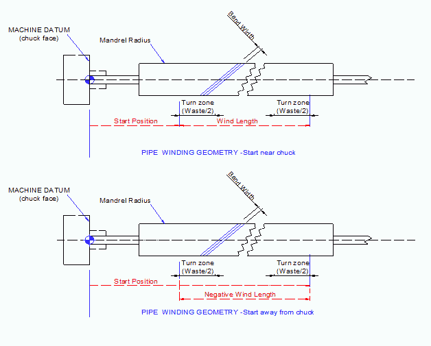
The start position can be at either end of the mandrel. To start away from the chuck and then initially towards it, use a negative Total Length of Winding (wind length in the lower diagram) For hoop winding, each repeat (layer) is one traverse of the carriage. If the repeats are an odd number, then the next helical layer will automatically swap ends of the mandrel to start. This ensures that the winding is always continuous.