Tee Piece Winding
 Cadfil Help contents
  Cadfil.com Home
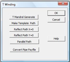
Cadfil has a number of specific modules for Windings Tee, these can be found on the 'T Winding' Option on the QuickCAD menu.
The are a numbers of stages:
1] Generate the mandrel surface definition and an envelope definition (see below). The envelope is a surface that is clear of the mandrel surface on which the machine will run without hitting the mandrel.
2] Create a 'template' winding path by steering it across the mandrel surface using 'friction'. See the topic Tee Template Path
3] Expand the template path (if required) using the symmetry tools as the T has 2 distinct symmetry planes.
4] Replicated paths parallel to the original path separated by a distance that is the bandwidth of the fibres.
5] Process the paths on the mandrel surface to create the 3D machine path (payout path) on the clearance envelope (surfaces).
6] Post-Process the payout to create instructions for the winding machine.
8] It is also possible to generate standard pipe winding programs for the cross piece. This can be modified and 'attached' to the T mandrel using a specific T option.

From the T Winding options pick the 'T Mandrel generate' Button.
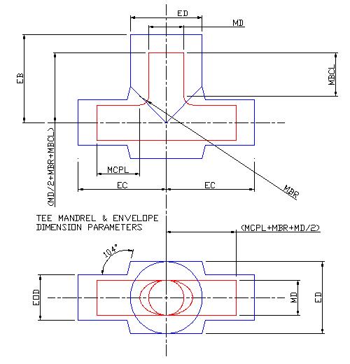
The figure below shows the T mandrel and envelope dimensions the actual dimension values in mm or inch are entered in a windows dialog.

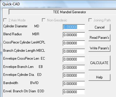
The data entry dialog is shown below.

Cylinder Diameter MD.
The cross-piece pipe and branch pipes are the same diameter.
Blend Radius MBR
This is the surface blend radius between cross piece and branch pipes. Typical values are between 0.25MD and 0.5MD
Cross-Piece Cylinder length MCPL
This is the length outside the blend area at each end (see diagram). The Cross piece total length is 2*MCPL+2*MBR+MD.
Branch Cylinder length MBCL
This is the length of the branch above the blend area (see diagram).
Envelope Cross piece length EC.
This is for the machine clearance, refer to the diagram. If the position of the machine wants to be further away (in length) from the mandrel centre the machine will then move on a circular plane at the end of the envelope. Caution is required as shaft collision could occur. This can be checked in the payout viewing options or in the post-processor output. EC must be greater than MCPL+MBR+MD/2 to be clear of the end of the mandrel, typically add a mandrel diameter.
Envelope Branch length EB.
This is for the machine clearance, refer to the diagram. If the position of the machine wants to be further away (in length) from the mandrel centre the machine will then move on a circular plane at the end of the envelope. This determines the furthest distance away the cross-feed axis will be from the winding axis.
Bandwidth BWID
This is the width of the fibre band to be used and is saved associated with parameters in the mandrel data.
Once entered the 'Write Params' option can be used to save the parameter data, for example to the file name1.par. This can be read back later using 'Read PArams' if there is a need to change the data. The 'calculate' button is clicked then to generate the mandrel data. You will be asked to give a name for the mandrel file, this will be saved with the .mnd extension, for example mytee1.mnd. After some calcualtion you will be asked for the mandrel name again it is best to use same name as the initial mandrel data has been processed further and is now not needed.
Envelope Branch Outer Diameter EOD
The leg usually requires quite a large clearance diameter (ED) to allow for the width of the payout eye. For this reason the outer end of the POE needs to be as narrow as possible to allow a smaller clearance. The branch cylinder has the same clearance diameter (ED) around the intersection area however outside this area a smaller clearance can be used (EOD), this should be as small as is practical to stop excess program motion that can lead to a loss of fibre tension. The transition zone from ED to EOD is conical with an arbitrary gradient of 4 (76 degrees).