Editing of Mandrel and Envelope X, R Data
 Cadfil Help contents
  Cadfil.com Home
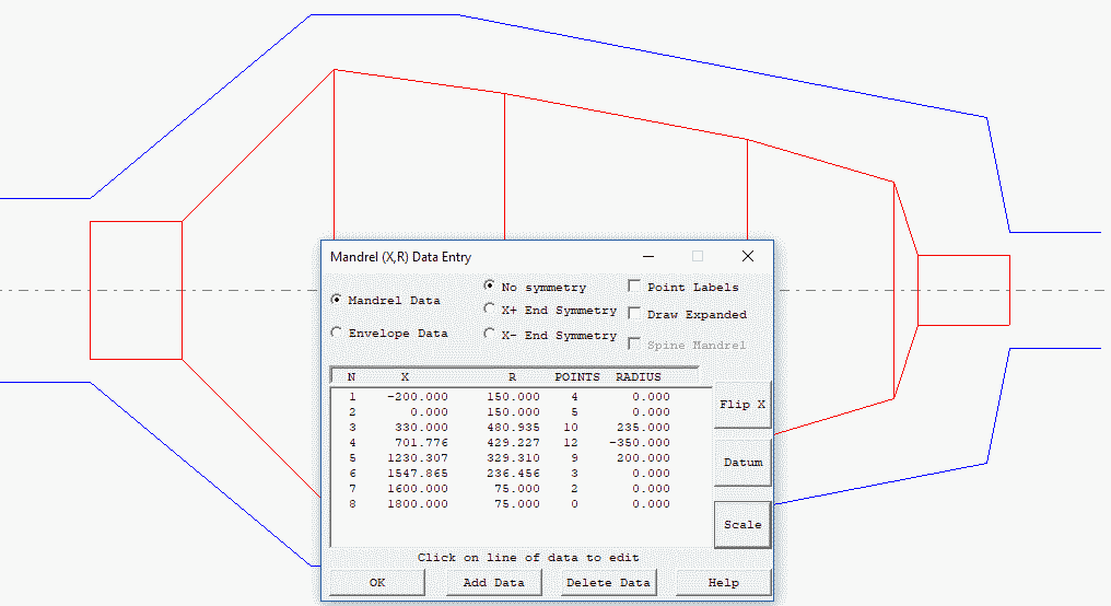
Creating mandrel or envelope data for axisymmetric shapes is done using the XR Data Entry Dialog Box, accessed from the Mandrel Edit or New mandrel options on the main menu. The buttons and features of this dialogue box are described in the sections below and an example illustrating the main features is given.
Mandrel Editor Dialog CAD Import / Export Menu
The mandrel editor has a menu as shown in the picture below. This is a number of Import / Export options to transfer CAD data using standard formats such as IGES , STEP and DXF which are described in other sections in the following links.
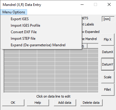
- Export Mandel and envelope via IGES file
- DXF file Profile Import
- IGES file Profile Import
- STEP file Profile Import
Menu Item - Expand (De-parameterise mandrel)
This option will remove any arcs and lines with divisions, and converts them all to just points connected by straight lines. If you wish to keep the parameterised versions, it will need saving as a separate file.
Manual mandrel point entry and editing
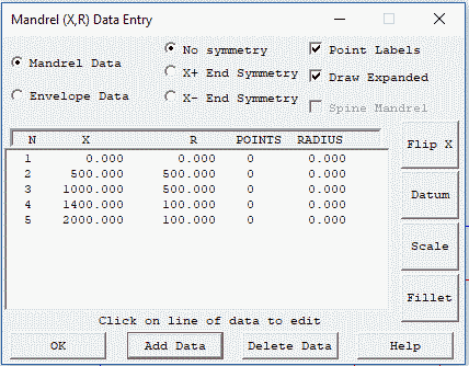
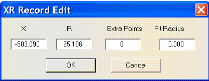
Looking at the dialog shown above, if we click the Add Data button the line entry dialog below pops up populated with some initial (zero) values.
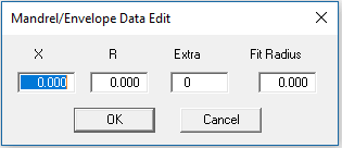
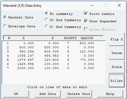
If we forget about the values Extra and Fit Radius for the moment and just enter the X and R values (X,R Coordinates), we can navigate from box to box with the mouse or the Tab keys. To accept each new line we click the OK button and then the Add Data button for the next set of values. In this way coordinates (0,0) (500,500) (1000,500) (1400,100) and (2000,100) are entered. This is the data shown in the first picture in this help topic and gives the red mandrel profile shown below.
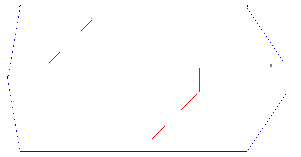
If We click the Fillet button we get the two dialogs shown below, to enter the fillet radius and the point number of the corner that is to be filleted. In this case we enter a fillet radius of -70 (minus because it is a concave/inside fillet) and select point number 4.
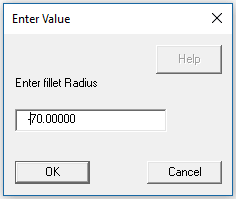
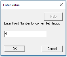
Having entered the two values the resulting fillet radius is shown in the picture below. We get the option to accept the change or abandon it. In this case we will accept the fillet operation.
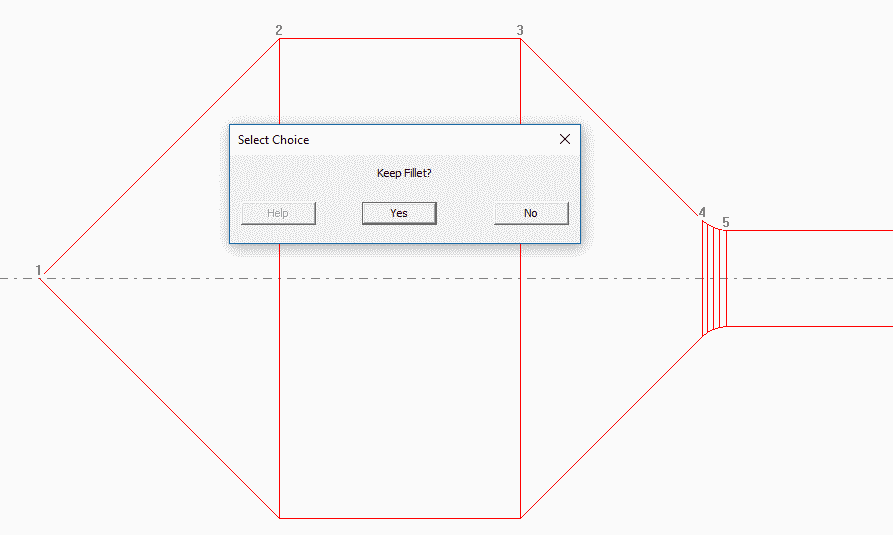
The fillet process was repeated by adding a Fillet of radius of +120 (positive as it is an external corner) at point number 3. Then by clicking on the first line of the data table we can edit this line adding 7 Extra points and a Fit Radius of 500. Adding an arc to point 1 fits an arc curve between point 1 and point 2, the number of interpolated points on the curve in this example being 7. The results of these changes can be seen in the two following pictures.
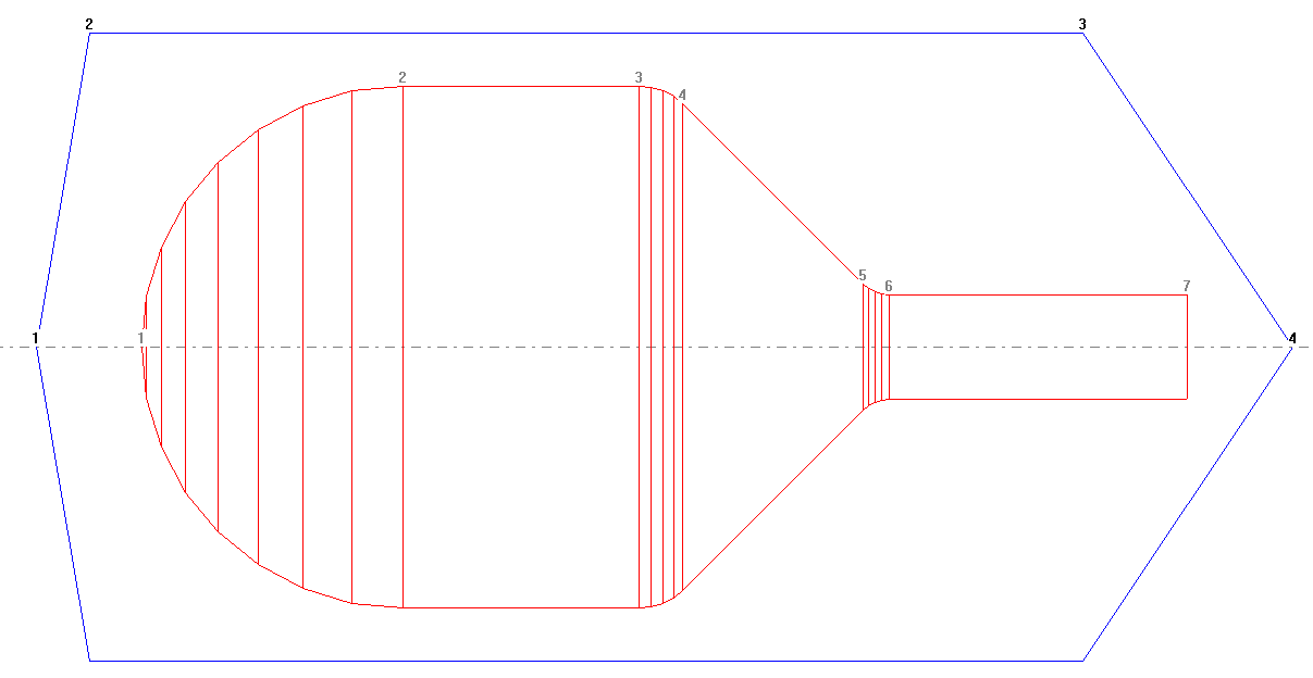
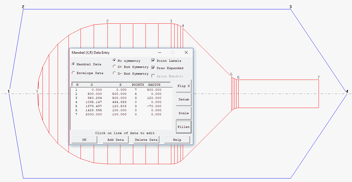
As a last step in this example the line from point 2 to point 3 is divided by adding 4 Extra points with a Fit Radius of 0.0 (a line), the results of which can be seen below.
Point Labels Check Box
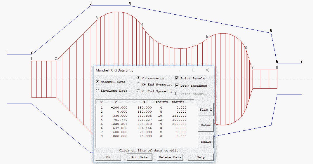
If this box is checked numbers are placed on the data points as can be seen the mandrel drawings below with the points/and expanded boxes checked and unchecked. These numbers match the point numbers in the mandrel or envelope data list in the edit dialog.
Draw Expanded Check Box
Mandrel or envelope data consists of basic data point and additional points that lie on lines or circular arcs between basic data points if Draw Expanded is checked this additional points are shown on the mandrel/envelope drawing in the graphics window
No Symmetry; X+ End Symmetry; X-end Symmetry; Buttons
These buttons set symmetry options The options are X- END to set a flag to say the mandrel (and envelope) is symmetric about the left hand X data position of the mandrel, X+ END to set symmetry about the right hand end, or NONE (the normal option). Note that for X+ symmetry the envelope must not have points with X values greater than the largest mandrel X position, and for X- symmetry the envelope should not have X co-ordinates less than the smallest mandrel X position.
Mandrel Data/ Envelope Data Radio Buttons
When these button are clicked the focus switches from editing Mandrel data to Envelope data. (Or visa versa) and the data in the Text Data List box also switches.
Text Data List Box
This area of the dialog shown in the top picture has 5 entries for each mandrel or envelope as selected with the Mandrel Data/Envelope Data Buttons These are a point number (see Point Labels), and X position, a Radial R position, Extra Points and Fit Radius.
The X & R positions are main data (x, y) points for the mandrel profile. The fit Radius is a circular arc to fit between this point and the next main data point. If this is the last point then the fit radius is ignored. The extra points are a number of X,R data points that are automatically created on the fit radius. If the fit radius is zero the extra points are created on a straight line. If the extra points value is zero then the fit radius is ignored. If fit radius is negative then the radius will be concave rather than convex.
Clicking on a line of data allows the values to be edited via a popup edit box shown below.
Add Data Button
This option pops up a row of four edit boxes shown above where the user can enter the four values X,R, Additional points and Fit radius. These data are then added to the mandrel or envelope.
Delete Data Button
The pops an edit box asking for the data point numbers to delete. The user can enter multiple points e.g. 1 3 5 Would delete points 1 3 and 5. Up to five lines of data can be deleted in one go.
Flip Button
The options turns the mandrel around, for example if this part was a gas cylinder the neck would go from the X+ end to the X- end or visa-versa. This is useful when a mandrel drawing is dimensioned from the wrong end compared to how it will be loaded into the filament winding machine.
Datum Button
This options allows the user to add a value (it may be positive or negative) to all mandrel and envelope positions to move its origin (zero position).
Scale Button
This option allows the user to multiply all values by a scale factor. So for example if the data was entered in inches but mm are required then enter a scale factor of 25.4 and all the values will multiplied by this factor and thus converted. The mandrel should then be saved with the updated data. The scale factor is not saved or retained in any way. Cadfil does not know the actual units used for the mandrel, these are just dimensionless units. If the units used for the mandrel do not match the linear units for the winding machine then conversion (gearing) factors must be specified in the post processor configuration.
Fillet Button
This option can be used to add a fillet radius to a sharp corner. The user is asked for the fillet radius and the point number for the corner. A successful fillet will delete the corner point and then add two new points at the ends of the fillet radius. Cadfil will only allow a fillet of lines, it will not fillet between arcs. If the fillet radius is too large such that it would swallow (totally remove) the lines being filleted then it will not be allowed. Give the fillet radius as negative for inside corners (concave) and positive for outside corners (convex). Fillets are created by default with 3 internal interpolated points (extra points) but you can edit this value if you wish.
Menu Item - Write IGES
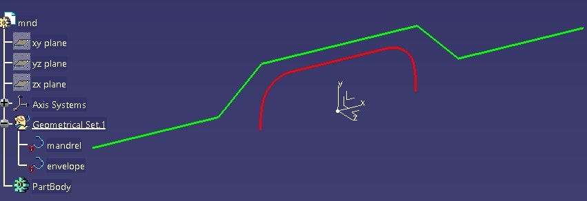
At Cadfil V9.46 a menu was added to the mandrel editor dialog, this can be seen in the picture below. The menu item Export IGES can be found on this menu. The options asked for a name of an IGES file and then writes the current mandrel and envelope as a pair of composite curves made up of lines and circular arcs. An example imported into Catia can be seen in a picture below also. The profiles are XY (i.e. XR) and in the Z=0 plane the units are assumed to be mm and zero position are as in Cadfil.

